
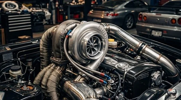
Key Takeaways / Quick Answer
- Turbo lag is the measurable delay (typically 0.5–3.0 seconds) between throttle input and peak boost delivery, caused by exhaust energy insufficient to accelerate the turbine wheel to its operational RPM range.
- Turbo spool time is the physical duration it takes the compressor wheel to reach its minimum effective speed (often 80,000–150,000 RPM on a street turbo), generating usable manifold pressure above atmospheric.
- Common root causes include oversized compressor housings, exhaust leaks pre-turbine, worn journal/ball bearings, boost leaks post-compressor, and incorrect A/R (area-to-radius) ratios on the turbine housing.
- Diagnostic tools needed: boost gauge, EVAP smoke machine, wideband O2 sensor, scan tool with live PIDs, and a calibrated mechanical pressure gauge to pinpoint the fault fast.
What Is Turbo Lag and Turbo Spool — The Real Engineering Explanation
If you’ve ever floored the accelerator and felt nothing happen for a beat before the car suddenly lunges forward, you’ve experienced turbo lag firsthand. It’s one of the most misunderstood phenomena in forced induction, and conflating it with spool time causes most DIY diagnostics to go sideways before they even start.
Let’s establish precise definitions that align with SAE International standards for turbocharger performance testing.
Turbo lag is the transient response delay — the gap between when the driver demands torque (throttle input) and when the turbocharger delivers sufficient boost pressure to meet that demand. This is fundamentally a thermodynamic and rotational inertia problem. The exhaust gas energy required to accelerate the turbine wheel from idle speed to peak efficiency speed simply isn’t available instantaneously.
Turbo spool or spool-up time is the mechanical event — the actual elapsed time for the compressor wheel to accelerate from its current rotational speed to the threshold RPM where it begins producing usable manifold pressure. On most OEM street turbos (think Garrett GT2052, Borg Warner EFR 6258), this threshold sits around 80,000–100,000 shaft RPM. Full-power racing turbos on 3.0L+ displacement engines may not hit peak efficiency until 130,000–150,000 RPM.
These two terms are related but not interchangeable:
- Spool time is a subset of the lag experience
- Lag includes spool time PLUS the time for boost pressure to build in the intake manifold AND the ECU’s fueling/ignition compensation response
- You can reduce spool time without eliminating lag if your intercooler volume is excessive or your boost pipes have large internal volume

The Physics of Turbo Spool: What’s Actually Happening Inside the Housing
Understanding why lag exists requires understanding the turbocharger as a rotating assembly — a shaft with a turbine wheel on one end and a compressor wheel on the other, spinning on either journal bearings or ball bearings, lubricated by engine oil at 45–65 PSI.
At idle, a typical turbo spins at 20,000–40,000 RPM. The compressor wheel isn’t generating meaningful pressure at this speed. When you demand full throttle, the following chain of events must complete before you feel boost:
- Throttle body opens → intake manifold vacuum drops
- ECU enriches fueling → more fuel combusted = more exhaust energy
- Exhaust gas enthalpy increases → higher mass flow and temperature at turbine inlet
- Turbine wheel accelerates → rotational inertia of the shaft assembly must be overcome
- Compressor wheel speed rises → begins compressing inlet air
- Manifold absolute pressure (MAP) increases → ECU begins advancing timing and increasing injector pulse width
- Power delivery ramps up → driver feels acceleration
Steps 3 through 6 represent the spool window. The moment of inertia of the rotating assembly is the dominant engineering variable here. Larger compressor and turbine wheels = more rotational mass = longer spool time. This is precisely why a GT35R will always spool slower than a GT2860RS on an equivalent engine displacement, regardless of how the rest of the system is set up.
The A/R Ratio — Most Overlooked Variable in Spool Tuning
The A/R ratio (Area-to-Radius) describes the geometry of the turbine and compressor housings and has a direct, quantifiable impact on both lag and peak power:
- Lower A/R turbine housing (e.g., 0.63 A/R): Exhaust gases are accelerated through a smaller cross-section, generating higher gas velocity at the turbine wheel. This produces faster spool at lower RPM — but creates backpressure and chokes the engine at high RPM.
- Higher A/R turbine housing (e.g., 1.01 A/R): Lower exhaust velocity at lower RPM = more lag, but the engine can breathe freely at high RPM for maximum peak power.
Most OEM turbos use A/R ratios between 0.48 and 0.72 for the turbine housing, optimizing for streetable spool characteristics. Aftermarket performance applications often go 0.82–1.06 A/R when chasing top-end power on engines above 400 HP.
Turbo Lag Diagnostic Troubleshooting Matrix
This table is the shop-floor tool you need before spending a single dollar on parts. Match your symptoms to the fault path and work down the probability column.
| Symptom | Most Probable Fault | Secondary Cause | Diagnostic Tool | Repair Priority |
|---|---|---|---|---|
| Lag only at low RPM, normal above 3,500 RPM | Turbo A/R too large for engine displacement | Low exhaust backpressure (cat delete without retune) | Boost gauge, dyno pull | Medium — tuning or turbo swap |
| Lag at ALL RPM ranges, no boost above 8 PSI | Boost leak post-compressor | Wastegate stuck open | EVAP smoke machine, boost pressure gauge | High — immediate |
| Gradual increase in lag over weeks/months | Worn journal bearings (shaft play >0.003″) | Compressor wheel erosion/blade damage | Turbo play inspection, visual wheel inspection | High — rebuild/replace |
| Lag with black smoke on throttle blip | Overfueling — ECU not seeing boost signal | MAP sensor failure | OBD-II live PIDs, MAP sensor test | High — sensor replacement |
| Lag with blue-grey smoke on boost | Oil entering compressor housing via worn seals | Clogged crankcase breather causing crankcase pressure | Oil consumption check, PCV inspection | Critical — seal failure |
| Lag only in cold ambient temperatures (<40°F) | Thick oil viscosity delaying bearing lubrication | Intercooler condensation restricting airflow | Oil viscosity check, intercooler inspection | Low-Medium — oil grade review |
| Sudden onset of severe lag with noise | Turbine wheel bearing failure or wheel contact | Foreign object ingestion (FOD) | Remove intake, inspect compressor wheel visually | Critical — DO NOT DRIVE |
| Lag with hunting/surging boost pressure | Compressor surge — map width too narrow | Diverter/BOV not venting properly | Boost gauge + wideband O2 | Medium — BOV/tune adjustment |
| Lag with low idle MAP reading (<10 inHg vacuum) | Exhaust leak PRE-turbine (manifold gasket) | Cracked exhaust manifold | Smoke test, stethoscope inspection | High — power loss fault |
| Normal spool but flat power delivery post-spool | Intercooler heat soak | Undersized fuel injectors (maxed duty cycle) | Intake temp sensor readings, injector duty cycle | Medium |
7 Proven Methods to Reduce Turbo Lag and Improve Spool Time
1. Match Turbo Frame Size to Engine Displacement
This is where most enthusiasts lose the plot. Bolt-on a GT3582 to a 2.0L four-cylinder and you’ll wait until 5,500 RPM for boost. The general rule from Garrett’s own application engineering documentation:
- 1.6–2.0L engine: GT25, EFR 6258, Precision 5558 (target spool: 2,800–3,500 RPM)
- 2.0–2.5L engine: GT28, GT3071, EFR 7163 (target spool: 3,200–4,000 RPM)
- 2.5–3.5L engine: GT30, GT3582, EFR 8374 (target spool: 3,500–4,800 RPM)
- 3.5L+: GT35, GTX3584RS, Precision 7675 (target spool: 4,200–5,500 RPM)
Chasing maximum peak power with an oversized turbo on a small-displacement engine is the single biggest cause of unacceptable street lag. Engineers at performance marques like Audi have solved this with twin-charging and electric auxiliary compressors — the engineering solutions behind some of the top Audi engines for excellent performance demonstrate precisely how compound forced induction eliminates the A/R compromise.
2. Upgrade to Ball Bearing Center Section
The factory journal bearing cartridge in most OEM turbos introduces 15–25% additional spool time compared to a ceramic ball bearing CHRA (Center Housing Rotating Assembly). Here’s why this matters mechanically:
- Journal bearings rely on a hydrodynamic oil film to support the shaft — at low oil pressure (cold start) or high shaft speeds, this film has greater friction losses
- Ball bearing assemblies reduce friction by 60–70% at low shaft speeds, allowing the compressor to accelerate faster with the same exhaust energy input
- Measured spool improvement: 200–400 RPM reduction in peak boost threshold on a typical GT28-class turbo
Ball bearing CHRA retrofits for popular turbos (Garrett GT28, GT30 series) run $280–$650 for the bearing assembly alone. Full turbo replacement with a BW EFR series (which ships with ball bearings standard) is the cleaner path if the OEM unit has >80,000 miles.
3. Eliminate Every Boost Leak in the System
A 10% boost leak can increase perceived lag by 30–40% because the ECU’s feedback loop compensates for the pressure loss by holding timing back. Use an EVAP smoke machine with an adapter fitted to the intake post-MAF and pressurize the system to 20 PSI (cap the BOV inlet). Smoke will exit from every leak point — intercooler pipe clamps, BOV flange welds, intercooler end tanks, intake manifold gaskets.
Common leak locations ranked by probability:
- Silicone coupler at intercooler outlets (loose T-bolt clamps)
- BOV/diverter valve diaphragm failure
- Intercooler end tank seam cracks (common on cast end tanks after heat cycling)
- Intake manifold gasket (especially post-head gasket repairs)
- MAP sensor O-ring
Speaking of intake manifold integrity — if you’re finding leak issues that extend deeper into the top end, it’s worth knowing how to diagnose and fix a blown head gasket like a pro before the combustion contamination causes compressor wheel corrosion from coolant vapor ingestion.

4. Optimize the Exhaust Path Pre-Turbine
Exhaust leaks upstream of the turbine are devastating to spool time — more so than boost leaks, because you’re literally throwing away the energy needed to drive the turbine wheel. A cracked manifold gasket or cracked cast iron manifold can reduce turbine inlet enthalpy by 12–18%, directly translating to slower spool.
Torque specifications for common exhaust manifold hardware:
| Application | Fastener Size | Torque Spec | Thread Treatment |
|---|---|---|---|
| Most 4-cylinder exhaust manifold studs | M8 x 1.25 | 18–22 ft-lb | Anti-seize compound |
| Most 6-cylinder exhaust manifold studs | M10 x 1.5 | 28–33 ft-lb | Anti-seize compound |
| Turbo flange to manifold (V-band) | — | 25–35 ft-lb (V-band clamp nut) | None — dry torque |
| Turbo flange to manifold (bolted, M10) | M10 x 1.5 | 30–35 ft-lb | Anti-seize |
| Downpipe to turbo outlet (V-band) | — | 25–30 ft-lb | None |
| Wastegate actuator bracket bolts | M8 x 1.25 | 16–18 ft-lb | Loctite 243 |
Always inspect manifold studs for elongation and replace with ARP studs (chromoly, 180,000 PSI tensile strength) if the originals show any corrosion or have been removed more than twice.
5. Install a Twin-Scroll Turbine Housing
If you’re running a 4-cylinder with paired firing order cylinders (1-4 and 2-3 share pulses), a twin-scroll manifold and matching twin-scroll turbine housing allows the exhaust pulses from each pair to enter the turbine wheel separately, preserving pulse energy rather than allowing it to destructively interfere in a single-scroll manifold.
Measured spool improvement over single-scroll equivalent: 300–600 RPM reduction in boost onset threshold. This is why manufacturers like Subaru (FA20), BMW (N55), and Volkswagen (EA888) all use twin-scroll architecture from the factory.
6. Anti-Lag Systems (ALS) — The Track Tool, Not the Street Solution
Anti-lag systems work by retarding ignition timing and maintaining throttle plate position at closed throttle, allowing unburned fuel and air to combust in the exhaust manifold and maintain turbine speed during lift-off. This keeps the turbo on boost during corners in motorsport applications.
The critical caveat: ALS raises exhaust temperature by 200–400°F above normal operating values. Turbine inlet temperatures on ALS systems routinely exceed 1,800°F (982°C). This accelerates:
- Turbine blade oxidation and erosion
- Turbine housing warping and cracking
- Catalytic converter destruction (usually immediate)
- Exhaust manifold thermal fatigue cracking
For street applications, ALS is not appropriate. It will destroy a turbine housing in 10,000–30,000 miles and void any warranty coverage. For stage rally or dedicated track use, budget $2,000–$5,000 per season for turbo maintenance when running ALS.
7. ECU Tune Optimization — The Lowest Cost, Highest Return Step
Before touching any hardware, a proper ECU tune calibrated to your actual turbo, injectors, and fuel can reduce perceived lag significantly by:
- Advancing ignition timing to the detonation threshold at partial load (generating more exhaust energy)
- Optimizing boost controller duty cycle for faster wastegate response
- Eliminating ECU safety retard events caused by knock sensor over-sensitivity
- Calibrating MAP sensor scaling so the ECU responds immediately when boost begins building
On a modern ECU (Hondata, Cobb Accessport, MoTeC M1), a skilled calibrator can reduce perceived spool RPM by 200–500 RPM without touching a single mechanical component. This is always Step 1 on any built engine before hardware upgrades are spec’d.
[GENERATE_IMAGE: “ECU tuning laptop connected to OBD-II port showing live boost pressure map, ignition timing tables, and wideband

